- English
- French
- German
- Portuguese
- Spanish
- Russian
- Japanese
- Korean
- Arabic
- Irish
- Greek
- Turkish
- Italian
- Danish
- Romanian
- Indonesian
- Czech
- Afrikaans
- Swedish
- Polish
- Basque
- Catalan
- Esperanto
- Hindi
- Lao
- Albanian
- Amharic
- Armenian
- Azerbaijani
- Belarusian
- Bengali
- Bosnian
- Bulgarian
- Cebuano
- Chichewa
- Corsican
- Croatian
- Dutch
- Estonian
- Filipino
- Finnish
- Frisian
- Galician
- Georgian
- Gujarati
- Haitian
- Hausa
- Hawaiian
- Hebrew
- Hmong
- Hungarian
- Icelandic
- Igbo
- Javanese
- Kannada
- Kazakh
- Khmer
- Kurdish
- Kyrgyz
- Latin
- Latvian
- Lithuanian
- Luxembou..
- Macedonian
- Malagasy
- Malay
- Malayalam
- Maltese
- Maori
- Marathi
- Mongolian
- Burmese
- Nepali
- Norwegian
- Pashto
- Persian
- Punjabi
- Serbian
- Sesotho
- Sinhala
- Slovak
- Slovenian
- Somali
- Samoan
- Scots Gaelic
- Shona
- Sindhi
- Sundanese
- Swahili
- Tajik
- Tamil
- Telugu
- Thai
- Ukrainian
- Urdu
- Uzbek
- Vietnamese
- Welsh
- Xhosa
- Yiddish
- Yoruba
- Zulu
Switching dies on a t bar roll forming machine without losing alignment
Switching dies on a t bar roll forming machine sounds straightforward—until you lose alignment mid-run and watch your scrap pile grow. A suspended-ceiling T-grid line running 0.12–0.3 mm PPGI at up to 20 m/min leaves almost no tolerance for positional error. Even a fraction of a millimeter of roller misalignment can warp a main tee profile or crack a pre-painted coating before the cut-off stage. This guide walks you through the real causes of alignment loss, proven corrective steps, and the machine features that protect your output when you need to change tooling fast.
Understanding the Challenges of Switching Dies on a T Bar Roll Forming Machine
There are clear reasons why die changeovers don't work. If you spot them early, you can avoid hours of fixing later on.
Mechanical Wear on Roller Stations
Normal production cycles are good for GB-Cr12 roller material, but removing and reinstalling dies over and over again wears out the shaft seats and locating keys. Even one station with 0.05 mm of seat wear can cause the finished profile to bow on an 18-station main-tee line. At every planned switch, check the shaft bores and keys.
Manual Measurement Errors
When technicians use handheld calipers without a fixed reference block, they add up errors at every station. When each roller is pressed against the same mechanical stop, a 45# steel shaft with a 50 mm diameter works as a solid reference. Most post-changeover rejects happen because this step is skipped, especially when production is tight.
Environmental Factors
For a ceiling t grid roll forming machine, Number 3: The forming frame's thermal expansion state changes when the temperature in the production hall goes up and down. Vibrations from presses or shears next to it can also move rollers that aren't fully locked in place. Before starting a new shift, always double-check the alignment again after the first 10 minutes of production. Both effects are small at first, but they add up over the course of the shift.
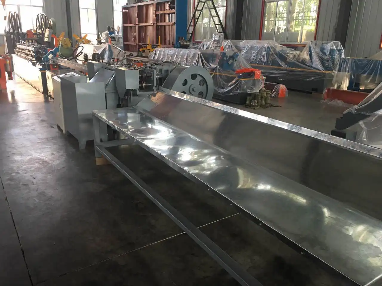
Principles and Best Practices for Maintaining Alignment When Switching Dies
To be good at alignment, you need three things: reference points that are always the same, torque checks on all of the fasteners, and a short test run before production starts up again.
Step-by-Step Changeover Method
Before you remove any fasteners, use a pen line to mark where the rollers are now. As you work from the exit end to the entry end, take out the outgoing die set one station at a time. Install the new set backward, making sure that each roller touches its stop before tightening. Do not guess the torque by feel; instead, use measured torque on all shaft collars.
Post-Mount Calibration
Put together the parts and then run a 500-mm sample strip of the same thickness of material that you will use in production. You can use a dial indicator to find the profile cross-section at five points along the strip. Check it against the limit for your profile picture. Before starting a full coil, make any station that is more than or less 0.1 mm off.
Real-World Reference
After using fixed reference blocks and a torque wrench on every die change, a mid-sized ceiling grid plant in Southeast Asia saw a 40% drop in scrap after the changeover. The solution cost less than the cost of rejecting profiles for one shift. This is a good sign for procurement teams that are deciding if buying tooling fixtures is worth the money.
Technical Specifications and Tools That Facilitate Die Alignment
The machine itself carries much of the alignment burden if it is spec'd correctly from the start. Here are the key hardware features worth evaluating before purchasing a ceiling T-grid line.
The ZTRFM suspended-ceiling T-grid roll forming line ships with the following verified specifications:
- Raw material: PPGI (0.12–0.3 mm for T-bar top) and GI (0.2–0.4 mm for T-bar bottom)
- Roller material: GB-Cr12, heat-treated for wear resistance
- Rolling stations: 18 for main tee; 16 for cross tee
- Shaft diameter: 50 mm, 45# steel
- Decoiler: 1.5-ton capacity, coil inner diameter 450–550 mm
- Work speed: 0–20 m/min with inline punching and cutting
For a t bar roll forming machine, these specifications establish the mechanical baseline that alignment depends on. A heavier shaft, harder roller material, and consistent station count all reduce the variables a technician must manage during a die change.
Beyond machine specs, three precision tools make a measurable difference in changeover quality: a dial indicator set mounted on a magnetic base for cross-section verification, a laser line projector for checking lateral roller parallelism across the full bed, and a torque wrench calibrated to the shaft collar specifications. Regular lubrication of roller bearings and scheduled replacement of worn locating keys prevent the gradual position drift that often goes unnoticed until scrap rates climb.
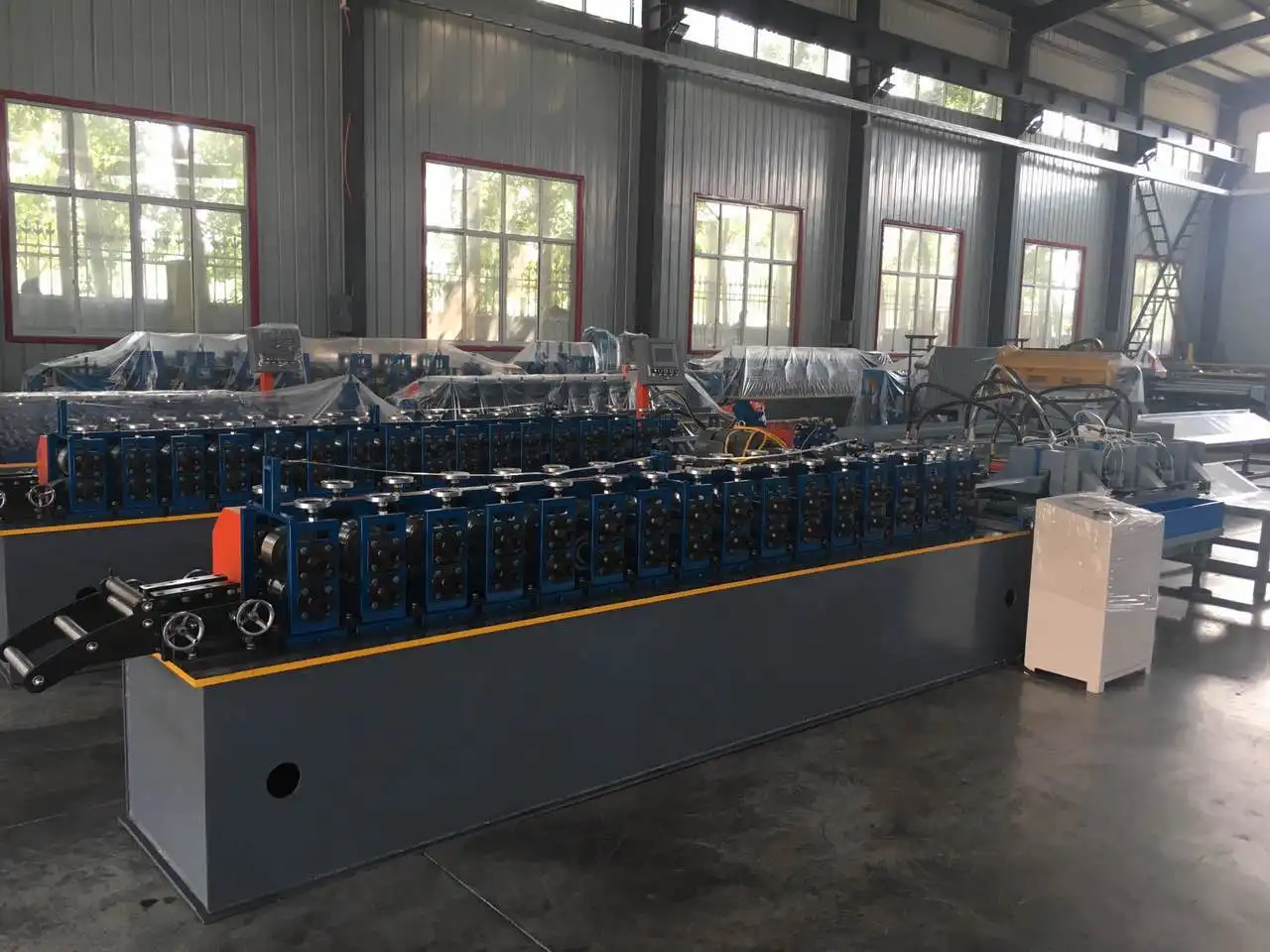
Comparing Manual vs Automatic Die Change Systems for T Bar Roll Forming Machines
It's not just a matter of technicality when deciding between manual and automated changeover. You have to think about cost and throughput.
Manual Die Switching
Manual methods are cheaper up front, and skilled installers can get direct feedback through touch. It takes longer, though. A skilled team needs 45 to 90 minutes to change a full die on an 18-station line, and each manual step increases the chance of uneven torque or missing reference alignment. Most of the time, manual switching is enough for shops that only run one or two profiles per week.
Automatic and Semi-Automatic Systems
Changeover systems that are driven by servos and controlled by CNC can cut the time it takes to swap dies on a similar line to less than 15 minutes. Position feedback loops make sure that each roller is in the right place before the interlock is released to start production. The precise gain is real, and digital input gets rid of the problem of estimating torque completely. If a plant makes three or more profiles per shift or if an OEM client needs to quickly switch between main tee and cross tee tools, automation is usually the better choice within 12 to 18 months of purchase.
Productivity and ROI Comparison
For a ceiling t grid roll forming machine, if the run speed is 20 meters per minute and the switch is done by hand, 1,500 meters of possible output are lost for each swap. That's 3,000 m of lost capacity every day, based on two changeovers per day. Most of that time can be recovered by automated systems, which is why makers of large amounts of ceiling grids prefer them.
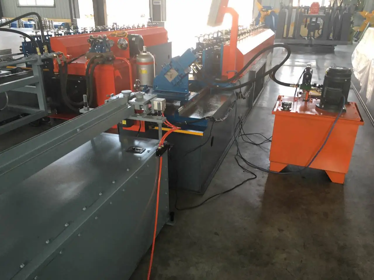
Common Troubleshooting Tips for Die Alignment Issues on T Bar Roll Forming Machines
Even with good procedures in place, alignment problems occasionally appear. Catching them early protects both material and tooling.
Warning Signs to Watch For
The three most common visual signs of a problem with station alignment are profile bow, edge wave, and flange width that doesn't stay the same. If a certain roller station makes strange noises or bangs on and off, it's likely because a bearing has moved out of its place. Do not ignore these sounds; a loose bearing can damage the shaft surface, which will cost a lot more to fix.
Quick Corrective Actions
If any of these signs show up, stop the queue right away. Use a dial indicator to measure the profile cross-section at the suspect station and mark it as separate. Once more, place the roller against its reference stop, apply the calibrated torque, and run a 500-mm test strip. Only then should production begin again. If the same station moves again during the same shift, it's likely that the locating key or bore needs to be replaced instead of being adjusted.
When to Escalate
If re-calibration doesn't fix the problem after two tries or if you can see cutting on the shaft, call the machine's maker for help. Through its relationship with Siemens cloud IoT, Cangzhou Zhongtuo offers remote diagnostic help. This lets engineers look at machine data without having to go to the site first.
Conclusion
A ceiling T-grid line built on a t bar roll forming machine keeps the quality of the product safe, cuts down on waste, and stays on schedule by keeping the dies lined up while the tools are being changed. It's easy to follow the rules. A short test run, fixed reference points, and calibrated torque should cover most mistakes made during the move. With that discipline and a machine that is made to very exact measurements, like an 18-station GB-Cr12 roller line with a 50 mm hardened shaft, most of the mechanical things that could go wrong are taken care of. Whether you use standard setups a lot or switch between main tee and cross tee tools several times during your shift, it's worth your time to learn how to do it right.
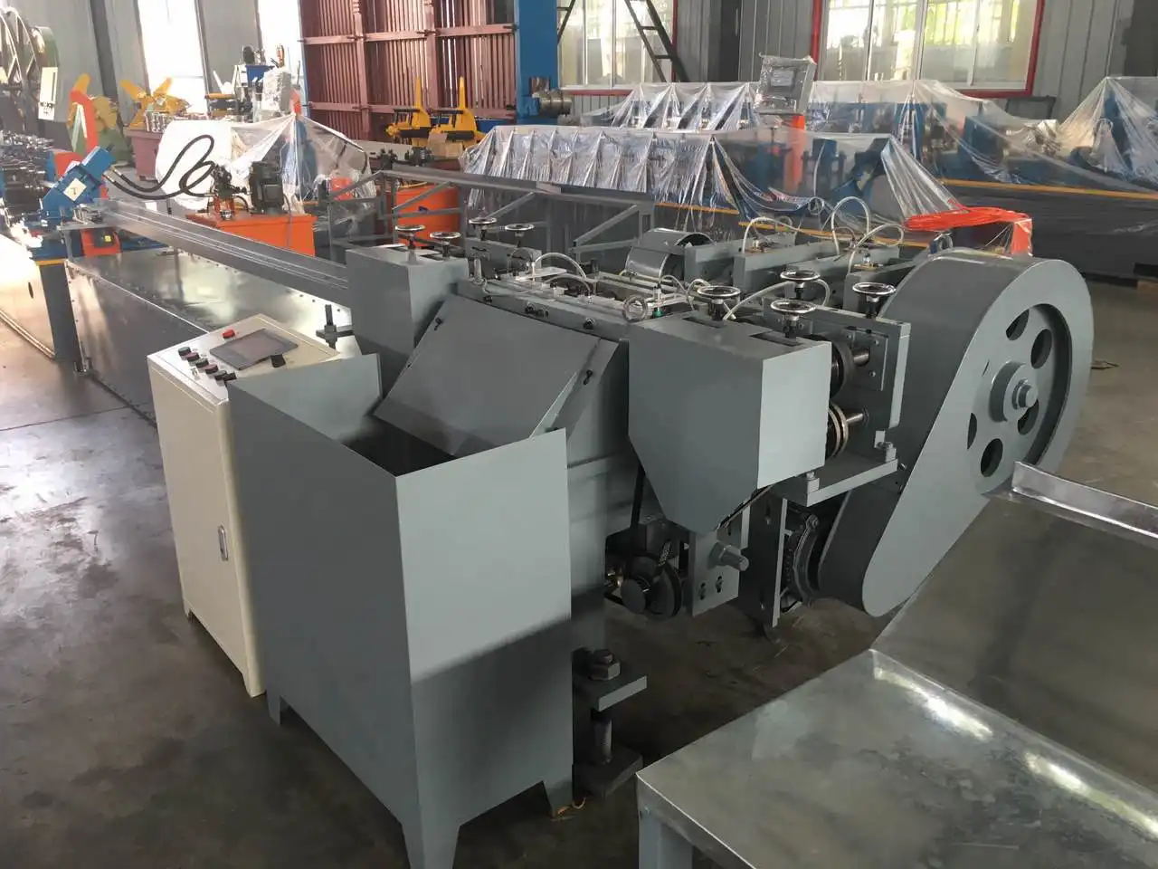
FAQ
Q1: How often should I check roller alignment on a T-bar forming line?
When you change the dies and every 10 minutes after a changeover, make sure the alignment is still correct. If your plant is open 24 hours a day and has more than one profile switch, it's a good idea to check the dial indicator when each shift starts, even if there isn't a formal die change.
Q2: Can I add automation to an existing manual die change setup?
Yes, most of the time. If the frame and shaft sizes are within the limits needed, servo feed and CNC position control can be added to lines that are already in use. Before buying retrofit parts, check with your machine's supplier to make sure they are compatible.
Q3: What is the best training approach for new technicians?
Before letting new technicians work on their own, they should be paired with experienced operators for at least five supervised changeovers. Use a written changeover guide that lists the torque requirements and how to measure them on a test strip. Video documentation of the right way to do the reference block procedure cuts down on differences between operators.
Q4: How does material thickness affect alignment sensitivity?
When the material is thinner, like 0.12 mm PPGI, even small misalignments have a bigger effect because the strip is less resistant to bending laterally. When you run your smallest gauge, you should keep your alignment tolerances tighter.
Get Precise T Bar Roll Forming Solutions from ZTRFM
There are ceiling T-grid lines that ZTRFM designed and built that are used in over 150 countries. They were first used in 2014. As a reliable t bar roll forming machine manufacturer, we offer full lines that include decoilers, formers, stackers, and spare parts. Our machines are certified by ISO 9001, CE, and CAS. Our tech team is ready to talk about your profile needs, changeover regularity goals, and output speed goals. To get a price or talk about technology issues, email us at zhongtuorollforming@gmail.com.
References
1. Halmos, George T. Roll Forming Handbook. CRC Press, 2006.
2. American Iron and Steel Institute. Cold-Formed Steel Design Manual. AISI, 2016.
3. Society of Manufacturing Engineers. Tool and Manufacturing Engineers Handbook, Volume 2: Forming. SME, 1984.
4. Schuler GmbH. Metal Forming Handbook. Springer, 1998.
5. International Organization for Standardization. ISO 9001:2015 Quality Management Systems — Requirements. ISO, 2015.
6. Zhang, W., & Li, J. "Dimensional Accuracy Control in Cold Roll Forming of Thin-Gauge Steel Profiles." Journal of Materials Processing Technology, 2019.